SQUIRREL-CAGE INDUCTION MACHINE
Motor and generator principle of operations
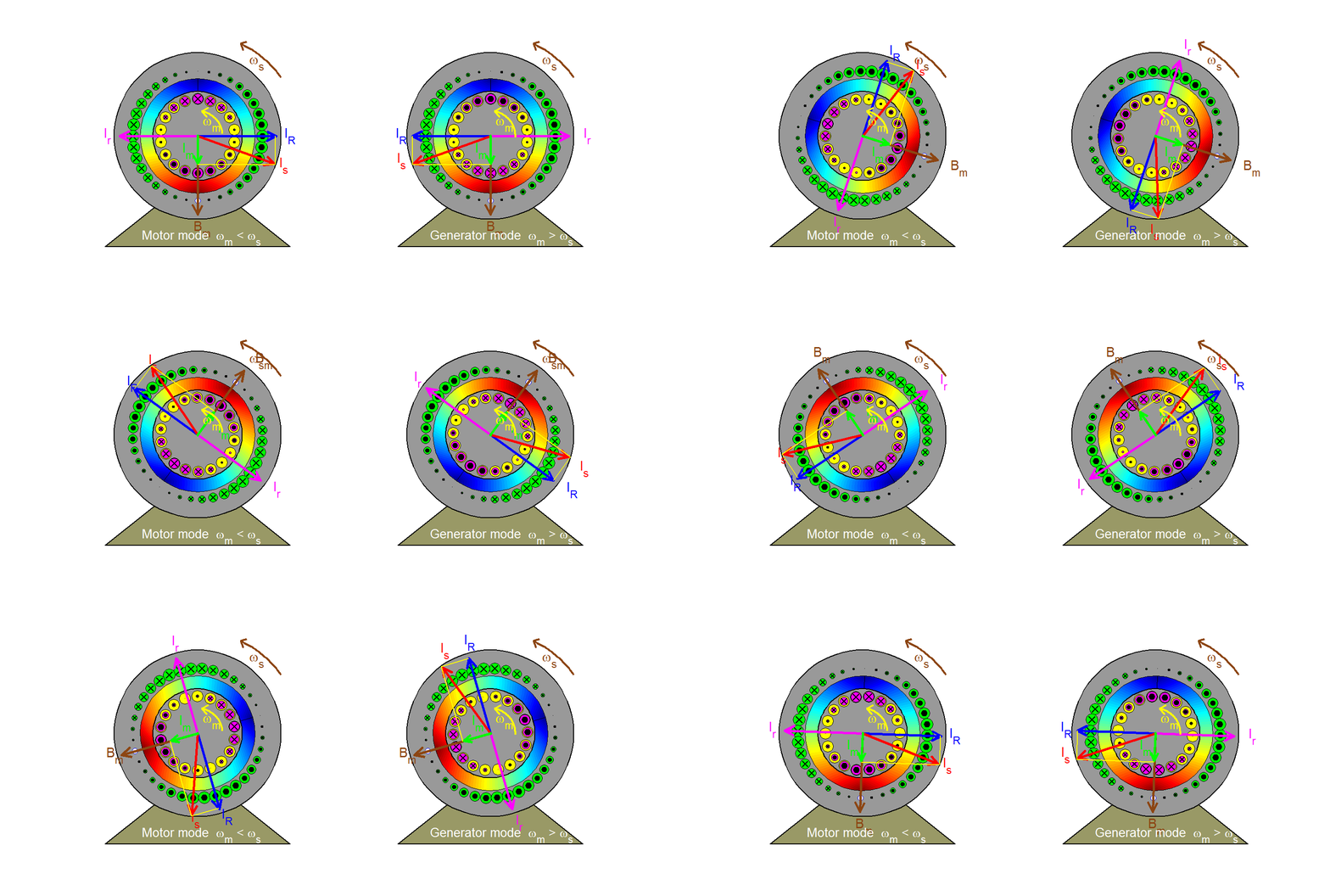
The rotating magnetizing field represented by the space vector Bm (or, equivalently by the magnetizing current Im) moves at the synchronous speed ωs with respect to a stator (or stationary) observer and at the slip speed ωsl = ωs - ωm with respect to a rotor observer. In the motor mode of operation where ωm< ωs, the rotor effectively moves backwards (clockwise) with respect to the field, inducing in each bar a voltage having the polarity indicated and a magnitude proportional to slip velocity u and to the field strength acting on the bar (in accordance with the flux-cutting rule v = Blu). Since the magnetic field is sinusoidally distributed in space, so will the induced voltages in the rotor bars. Ignoring the effects of rotor leakage ( i.e. assuming that the rotor is purely resistive), the resulting rotor currents are in phase with the induced voltages and are thus sinusoidally distributed in space varying sinusoidally in time at slip frequency; they may then be represented by the space vector Ir which rotate at the slip speed ωsl with respect to the rotor and at synchronous speed ωs with respect to the stator. Because Bm cannot change with a fixed stator input voltage (in accordance with Faraday's law), a stator space vector IR is created in order to compensate for the rotor effects so that the resultant stator current becomes Is = IR + Im. The electromagnetic force exerted on a rotor bar can be derived from the f = Bli rule and it is acting in the positive or anticlockwise direction (same as rotor speed) in the present case of a motor. The resultant torque developed on the rotor also acts in the same direction. Follow the path taken by one rotor bar as it travels around, observing the polarity and magnitude (described by the size) of the bar current.
In the case of a generator where ωm > ωs, all polarities and directions are reversed as can be observed in the right figure (except for the magnetizing component).
