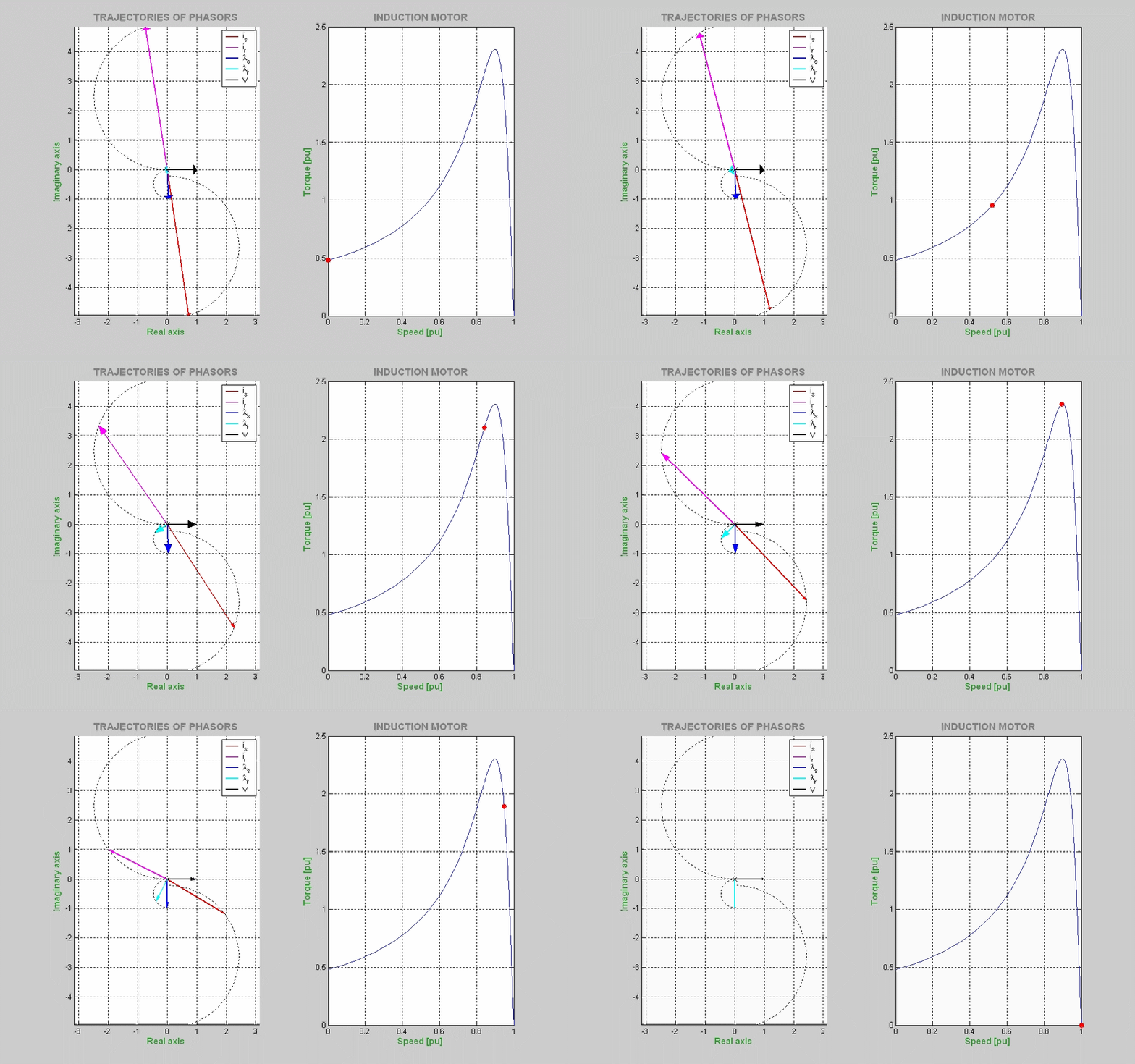
PHASOR DIAGRAM OF THE INDUCTION MOTOR
The steady-state
characteristics of an induction motor are described by means of
phasors which are computed using the standard
equivalent circuit and are then plotted in the complex plane in a speed range
from standstill to synchronous. The input voltage (black) is chosen as
reference; the stator and rotor currents and the stator and rotor fluxes are
shown. The trajectories of these phasors are
seen to
approximate portions of circles. The corresponding torque-speed curve is also
plotted.
